

Domestic typic NC system is FANUC and SINUMERIK
Now we give a comparison and conclusion of excircle turning in FANUC 0i and SINUMERIK 802s/c 、 802D
Environment : Swan simulation software
G71 Excircle rough turning canned cycle
G71U(△d)R(e)
G71P(ns)Q(nf)U(△u)W(△w)F(f)S(s)T(t)
N(ns)……
………
.F__ Program segments from ns to nf specify moving commands from A to B
.S__
.T__
N(nf)……
△d: Cutting depth(radius specifing)
Sign symbol is not specified. Cutting direction is determined by direction of AA',and it will not change before a value is specified.FANUC system parameter ( NO.0717 ) specifing.
e: Travel of back off
This command is state command.It will not change before a value is specified. FANUC system parameter ( NO.0718 ) specifing.
ns: First segment number of finish maching shap program.
nf: Last segment number of finish maching shap program.
△u: Distance and direction of finish machining obligated amount in X direction. ( diameter/radius )
△w: Distance and direction of finish machining obligated amount in Z direction.
As the following Fig shows, finish maching shape from A to A'to B is determined byprogram,and finish machining obligated amount △ u/2 and △ w is obligated in specified area turned by △ d(cutting depth).
Fig .1
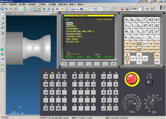
Fig. 2
M03S1000
T0101
G0X70Z2
G73U5W0R4
G73P10Q11U0.2W0.1F0.1
N10G01X50Z0
G3X40Z-15R22
G2Z-45R25
N11G1Z-50
G70P10Q11
G0X100Z200
T0100
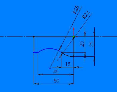
Fig . 3
Use the cycle to machine figure set by subprogram in the direction parallel to coordinate axis, and process portrait and cross direction machining, and process inside and outside figure machining.
You can select different cutting techincs : roughing 、 finish machining or Integration machining. If cutter collision won't be occurred you can call it in any place. Before calling cutter compensation parameter must have been activated in the used program.
Fig . 4
Diameter programming command G23 must be effective.
System must has installed SGUD.DEF.
You can call this cycle from third program interface in program nesting at most ( two level nesting ) .
| parameter | meaning , number range |
| R105 | Machining mode : numerical value 1...12 |
| R106 | Allowance for finish , unsigned |
| R108 | Cut-in depth , unsigned |
| R109 | Cut-in angle of roughing |
| R110 | Back off quantity of roughing |
| R111 | Feeding rate of roughing cutting |
| R112 | Feeding rate of finish cutting |
R105 parameter of machining mode. Use parameter to conform following machining modes:
Portrait machining / cross direction machining
Interior machining / exterior machining
Roughing / finish machining / Integration machining
Feeding is processed in the direction of cross direction axis when portrait machining, while feeding is processed in the direction of portrait axis when cross direction machining.
value |
portrait/ cross direction |
exterior/ interior |
roughing / finish machining / Integration machining |
| 1 | portrait | exterior | roughing |
| 2 | cross direction | exterior | roughing |
| 3 | portrait | interior | roughing |
| 4 | cross direction | interior | roughing |
| 5 | portrait | exterior | finish |
| 6 | cross direction | exterior | finish |
| 7 | portrait | interior | finish |
| 8 | cross direction | interior | finish |
| 9 | portrait | exterior | Integration |
| 10 | cross direction | exterior | Integration |
| 11 | portrait | interior | Integration |
| 12 | cross direction | interior | Integration |
R106 Parameter of allowance for finish
The machining before allowance for finish is roughing. If allowance for finish is not set, roughing is processed all the way till final figure.
R108 Cut-in depth parameter. Set maximal cut-in depth of roughing, but the maximal cut-in depth of current roughing is computed automatically by cycle.
R109 Cut-in angle of roughing
R110 Back off quantity parameter of roughing. Back off from figure after roughing parallel to axis, then return to initial point by G0. back off quantity is conformed by parameter R110.
R111 Parameter of roughing feeding rate. The parameter is ineffective when machining mode is finish machining
R112 Parameter of finish machining feeding rate. The parameter is ineffective when machining mode is roughing.
Workpiece figure to be machined is set in a subprogram, and cycle is called through subprogram name under parameter _CNAME.
Figure is composed with line or arc, and can be inserted by fillet and chamfer. The arc set can be quarter round at most. The programming direction of figure must be accordant with machining direction selected when finish machining.
For that figures whose machining mode is "endface 、 exterior figure machining", you must programme along direction from P8(35,120) to P0(100,40). The arrived position before sequential procedure starts: position is optional, but it must be ensured that cutter collision will not be occurred when back initial point of figure from this position.
This cycle has following sequential procedure:
Use G0 to return to initial point in the direction of two axis at the same time ( interior computation ) .Deepness feeding is processed according to angle set in parameter R109. Return to crossing point in direction parallel to coordinate axis by using G1 and feed rate under R111. Use G1/G2/G3 to process roughing according to feed rate set by parameter R111 till machining to last point along "fiture+ allowance for finish". Back off according to quantity of back off set in R 110 in each axis direction and return by G0.Reoeat above procedure till machining to last depth.
Use G0 to return to initial point of cycle machining separately according to different axis. Use G0 to return to initial point in the direction of two axis at the same time. Use G1/G2/G3 to process finish machining according to feeding rate set by parameter R112 along figure.
When finish machining, nose radius compensation activated automatically inside cycle. And initial point is computed automatically. When roughing, two axis return to initial point together; When finish machining, return to initial point separately according to different axis, and the first to run is cutting feed axis.
"Integration machining" is after last roughing, and dose not return to initial point of interior computing any more.
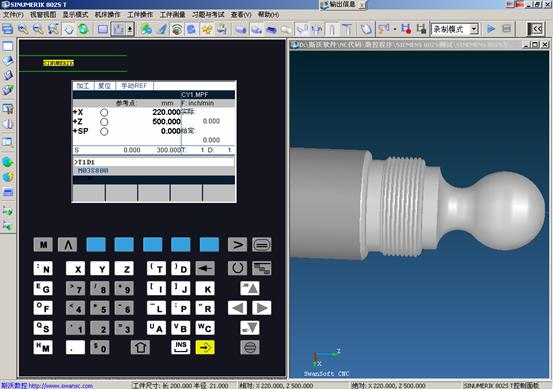
Fig . 5
Main program :mpf
T1D1
M03S800
G0X50Z2
_CNAME="L42"
R105=1 R106=0.3 R108=2 R109=7
R110=1.5 R111=0.4 R112=0.25
LCYC95
R105=5 R106=0
LCYC95
G0X200Z200
T1D0
T3D1
G0X40Z-43
R100=38 R101=-45 R102=38 R103=-60
R104=1.5 R105=1 R106=0.2 R109=2
R110=3 R111=0.975 R112=0 R113=4
R114=1
LCYC97
G0X100
Z100
T3D0
M05
M02
L42.spf
G1X0Z0
G3X20.8Z-25.8K-15I0
G2X31.6Z-39.5CR=8
G1Z-45
X35
X38Z-46.5
Z-58.5
X35Z-60
Z-65
X39
X42Z-66.5
Z-75
M02
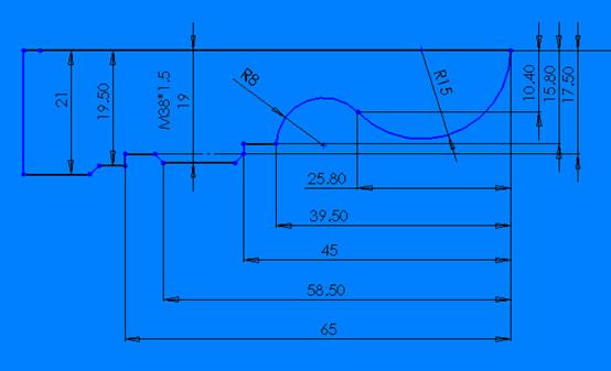
Fig . 6
Chamfers are al 45*1.5
CYCLE95(NPP,MID,FALZ,FALX,FAL,FF1,FF2,FF3,VARI,DT,DAM,_VRT)
| NPP | String | Name of contour subroutine |
| MID | Rcal | Infeed depth (enter without sign) |
| FALZ | Rcal | Finishing allowance in the longitudinal axis (enter without sign) |
| FALX | Rcal | Finishing allowance in the transverse axis (enter without sign) |
| FAL | Rcal | Finishing allowance according to the contour (enter without sign) |
| FF1 | Rcal | Feedrate for roughing without undercut |
| FF2 | Rcal | Feedrate for insertion into relief cut elements |
| FF3 | Rcal | Feedrate for finishing |
| VARI | Rcal | Machining type Range of values: 1 ... 12 |
| DT | Rcal | Dwell time fore chip breaking when roughing |
| DAM | Rcal | Path length after which each roughing step is interrupted for chip breaking |
| _VRT | Rcal | Travel of retraction from contour when roughing, incremental (to be entered without sign) |
Using the rough turning cycle, you can produce a contour, which has been programmed in a subroutine, from a blank by paraxial stock removal. The contour may contain relief cut elements.
It is possible to machine contours using longitudinal and face machining, both externally and internally. The technology can be freely selected (roughing, finishing, complete machining).
When roughing the contour, paraxial cuts from the maximum programmed infeed depth are programmed and burrs are also removed parallel to the contour after an intersection point with the contour has been reached. Roughing is carried out up to the programmed finishing allowance.
The starting position is any position from which the contour starting point can be approached without collision.
The cycle starting point is calculated internally and approached with G0 in both axes at the same time.
The paraxial infeed to the current depth is calculated internally and approached with G0.
Approach of paraxial roughing intersection point with G1 and at feedrate FF1.
Rounding parallel to the contour along the contour + finishing allowance with G1/G2/G3 and FF1.
Retraction by the amount programmed under _VRT in each axis and retraction with G0.
This sequence is repeated until the total depth of the machining step is reached.
When roughing without relief cut elements, retraction to the cycle starting point is carried out axis by axis.
Fig . 7
Main program :
T1D1
M03S800
G0X0Z2
CYCLE95("L18",1.5,0.3,0.3,0.2,0.2,0.2,0.2,9,0,0,1)
G0X100Z100
T1D0
T2D1
G0X32Z-30.5
G1X27
G0X100
Z100
T2D0
T3D1
G0X28Z-14
CYCLE97(1.5,3,-16,-27.5,30,30,2,2,1.35,0.1,0,0,3,2,3,1)
G0X100
Z100
T3D0
M05
M02
L18.spf
G1X0Z0F0.2
G03X20Z-10CR=10
G1Z-16
X27
X30Z-17.5
Z-30.5
X40
Z-35.5
G02Z-50CR=20
G1X50Z-58
Z-70
RET
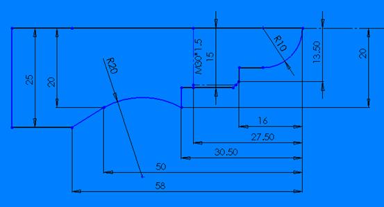
Fig . 8
Chamfer 45*1.5